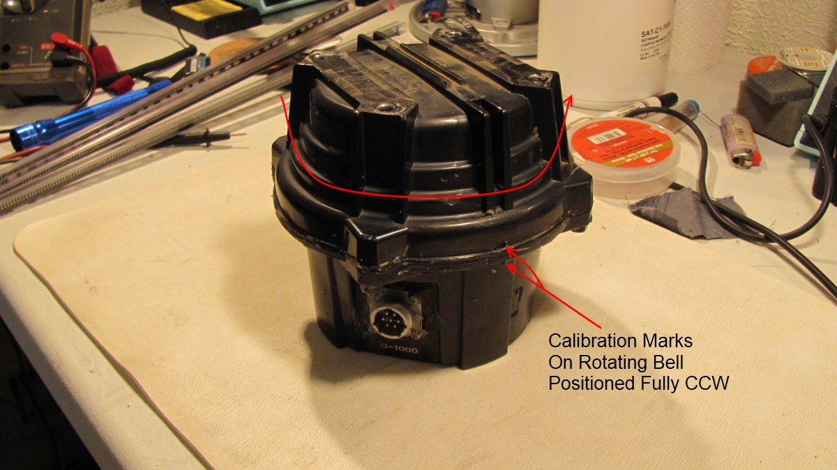
Step 1: Operate the rotor to it's fully CCW position.
Amateur Radio Station
WC0M
(Formerly: WC0EM, WF0GM)
Repairing a Yaesu G-1000DXA Rotor
(Part 1 of 2)
The following is my
experience with a faulty Yaesu G-1000DXA Rotor, and how I repaired it.
Hopefully this account will help someone else repair their rotor if they
encounter this same problem.
One day my azimuth indicator
pointer went wacko on my rotor controller when it was busy turning my antenna.
What I mean is that the pointer went berserk, like it had a mind of its own! I
noticed that the problem was its worst between 0 and 270 degrees while turning
the antenna counter clockwise. The pointer would actually move clockwise, while
the antenna was rotating counter clockwise! If I continued to advance the rotation CCW,
the pointer would eventually move in the proper direction and "catch up" to
where it should be on the dial. At first it did not always do this. But after a
while, it was clear that the problem was not going to go away, because it became
worse over time.
I am by no means an expert on these rotors, so if you do not have the same problem that I had, please don't ask me about it.
I had a real hard time finding much detail on the web about the problem described above. This page is the result of the lack of information out there concerning this repair. Hopefully it will help someone else fix their rotor having the same problem, and save them some grief.
After looking at the schematic, my best bet was that the potentiometer inside the rotator housing could be wearing. If there was an "open" somewhere along the path of the wiper, an incorrect voltage would be fed back to the controller. This is what turned out to be my problem. The following is my description of how I fixed it.
If you do not have the manuals, download them from the links below. I will refer to them during this discussion.
Download the User Manual here
Download the Service (Technical) Manual here
I recommend that you read
through these instructions before taking things apart.
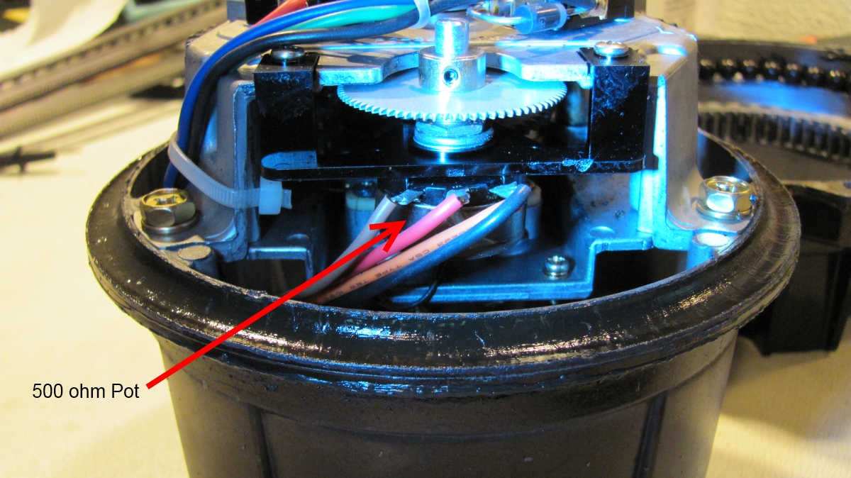
Start by looking at the
schematic on page 16 of the User Manual. At the top of the page is shown the
rotator unit inside of a box drawn with a dashed line. Locate VR4; a 500 ohm
potentiometer. This is the potentiometer that was giving me a problem. Note that
the three leads of the pot are connected to pins 1, 2, and 3 of the 7-pin
connector (item #7 in the Service Manual) on the rotor housing. You should measure full resistance across pins 1
and 3. When the rotor is fully CCW, resistance is maximum across pins 1 and 2,
and minimum across pins 2 and 3. As the rotor is turned CW, the resistance
across pins 1 and 2 will decrease, while the resistance across pins 2 and 3 will
increase. Therefore the feedback voltage to the controller will
increase/decrease.
Look for item #41 in the blowout drawing on the Rotator Section page of the Service Manual. This is the part that you will need to replace. Refer to the Service Manual for the item numbers indicated throughout these instructions.
I made this repair in January
of 2012. Here is the contact information that was good at that time:
I called Yaesu Tech Support (8am to 5pm PST) at
1-714-827-7600. The part number listed in the manual for the 500 ohm pot
was Q9000420. But when I asked for the part, they gave me a
substitute number: S8101678.
I also ordered a new pilot lamp for the controller. In the manual this was
part number Q1000068 but this also had a substitute number: S8101959.
Download the original full instructions in a single file in .pdf format
HERE
Update
July 2015! Before you begin:
Please download and read comments made by Scott, AC8DE.
Thanks to Scott for his contribution to this discussion.
Scott makes a very good point concerning hitting the hard stop of pot VR4.
That is something that you really should avoid!
Download his comments and instructions
HERE
Download the updated full instructions in .pdf format with Scott's comments imbedded in the discussion HERE
Step 1: Operate the rotor to it's fully CCW
position.
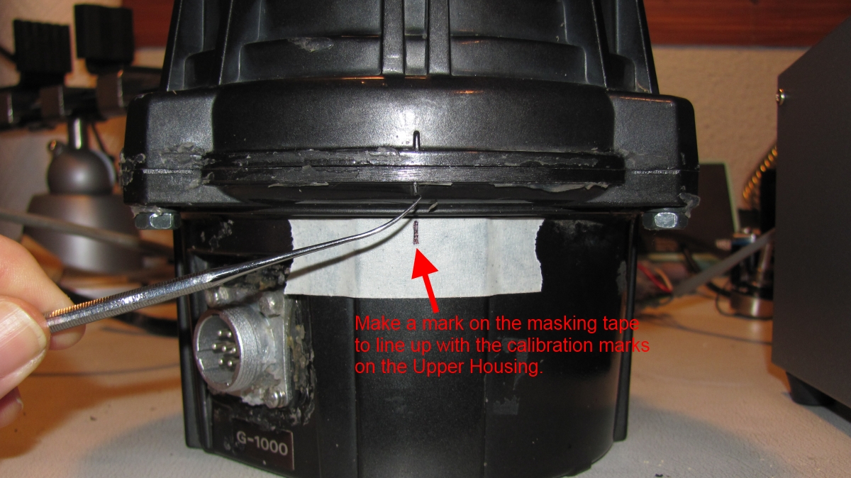
Step 2: Put a piece of masking tape on the Lower Housing (item #1
in the Service Manual) and mark the position of the rotor with the alignment
marks on the Upper Housing (item #2 in the Service Manual).
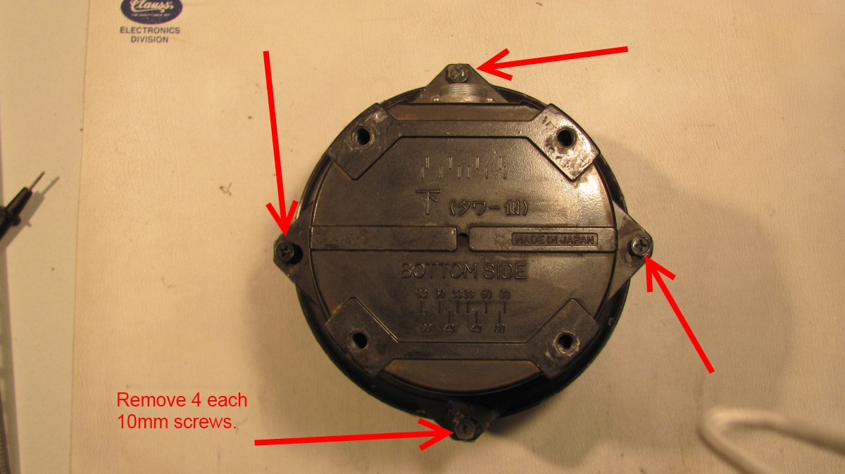
Step 3: Flip the rotor over and using a 10mm wrench remove the 4
screws holding the bottom bearing race to the moving bell.
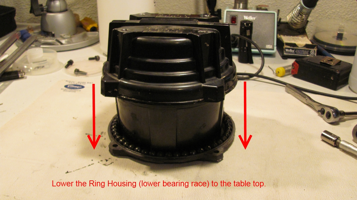
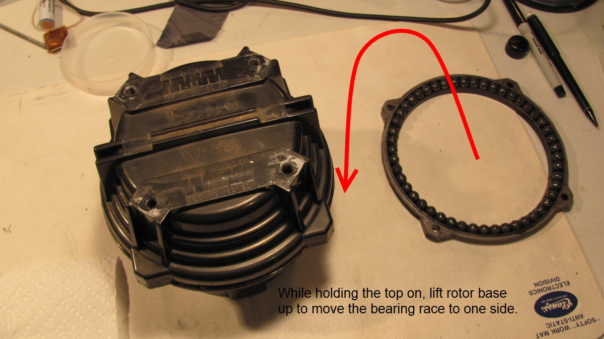
Step 4: Carefully flip the rotor back to top side up, while holding the bearing
race together as if the screws had not been removed.
Then carefully lower the race along with the 49 ball bearings down to the table
surface. Now without taking the top off, lift the base of the rotor up out of
the center of the lower bearing race, and set
the race to one side.
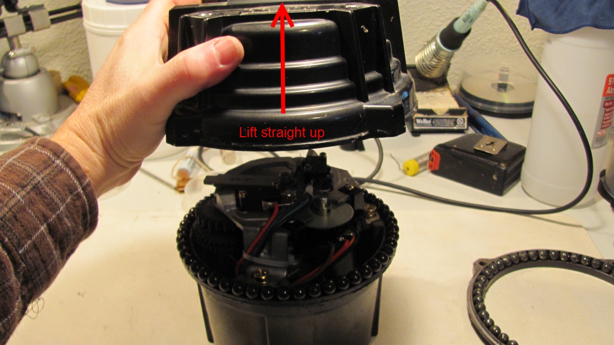
Step 5: Carefully lift the top of the rotor straight up to disengage the gears,
then tip it over top down onto the table top.
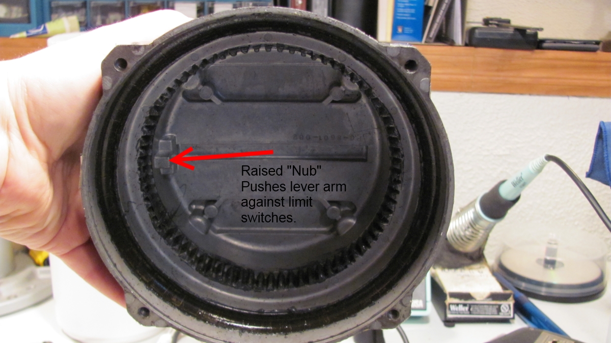
Notice the nub in the aluminum Upper Housing that pushes the lever arm (item
#31, Rotation Limiter) against the limit switch.
When reassembling the rotor, you will need to do it in two steps because of the
spring action of the limit switch.
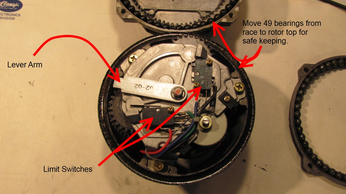
The way this works is, the rotor must turn 360 degrees for the nub to push
against the other side of the lever when rotating the opposite direction. This
in turn will cause it to push up against the other limit switch when it turns
another 90 degrees. Thus you get 450 degrees of total rotation in one direction
before a limit switch is activated. Don't worry about this for now, I'll give
you details on how to get it back together later.
Remove the 49 ball bearings from the rotor base and place them onto the race
section of the over-turned Upper Housing for safe keeping while performing the next steps.

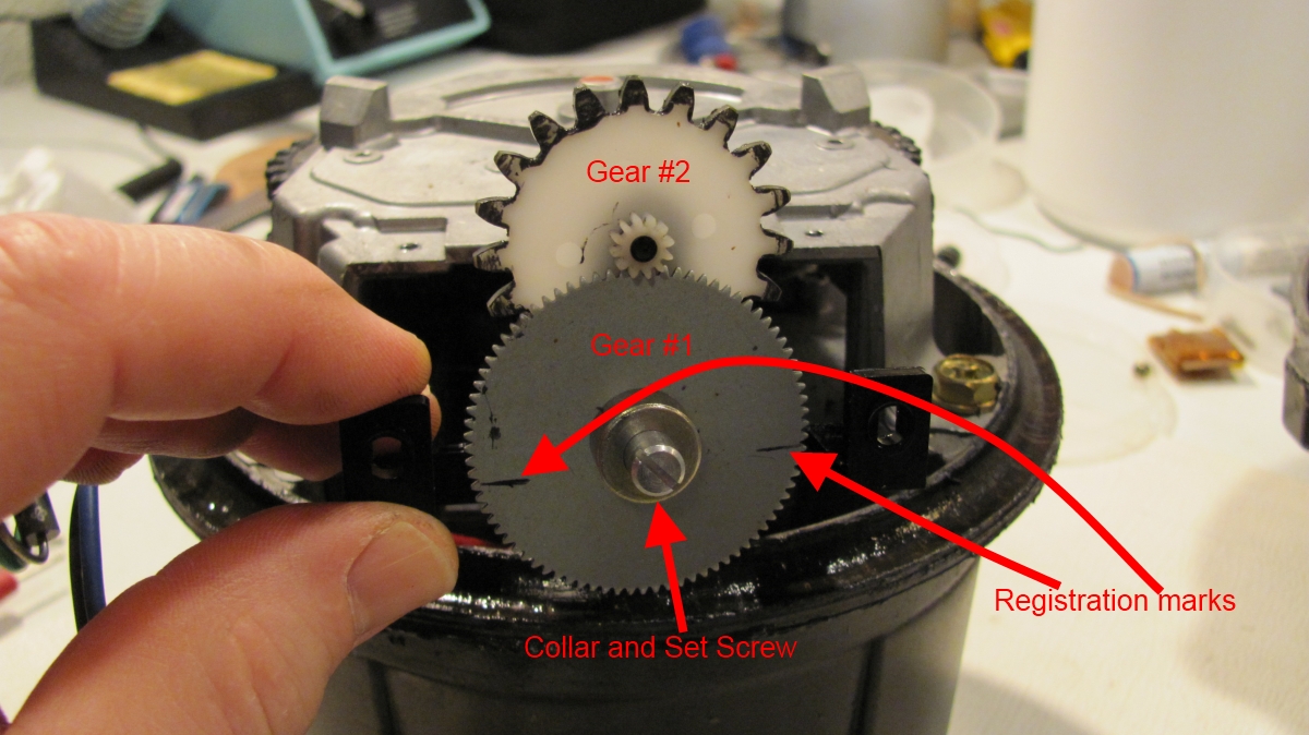
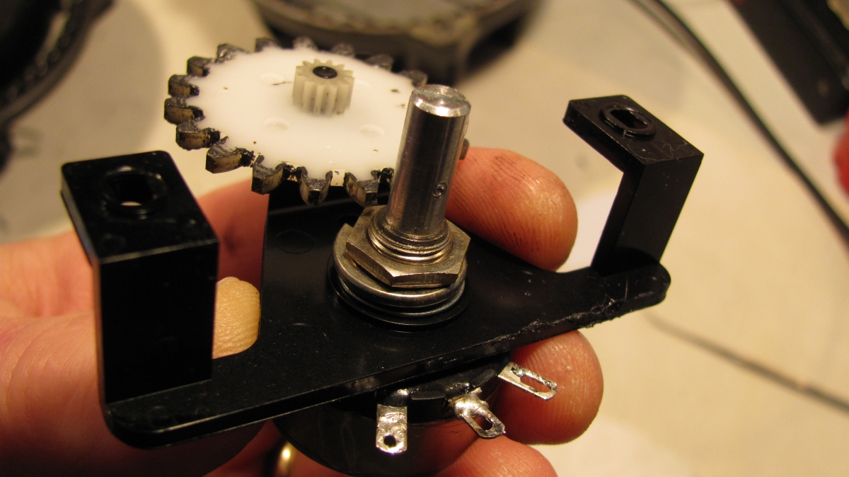
Step 6: Locate the 500 ohm position feedback potentiometer. It may
be a good idea to mark the position of Gear #1 (item # 45) with a fine point
marker to make it easier to see its position during reassembly. See the photo in
this step, and in step 8.
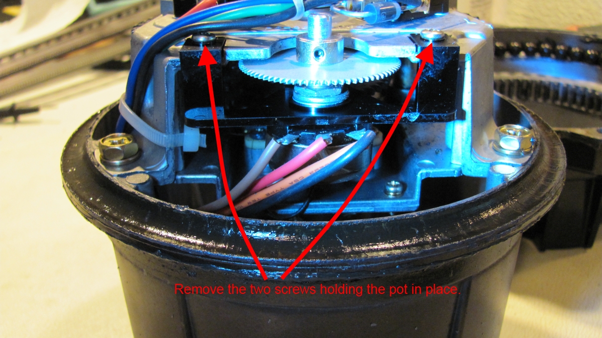
Step 7: Remove the two screws on the plastic Pot Mounting Plate (item #39)
that hold the pot in place on the Upper Gear Box Plate Assy. (item #33).
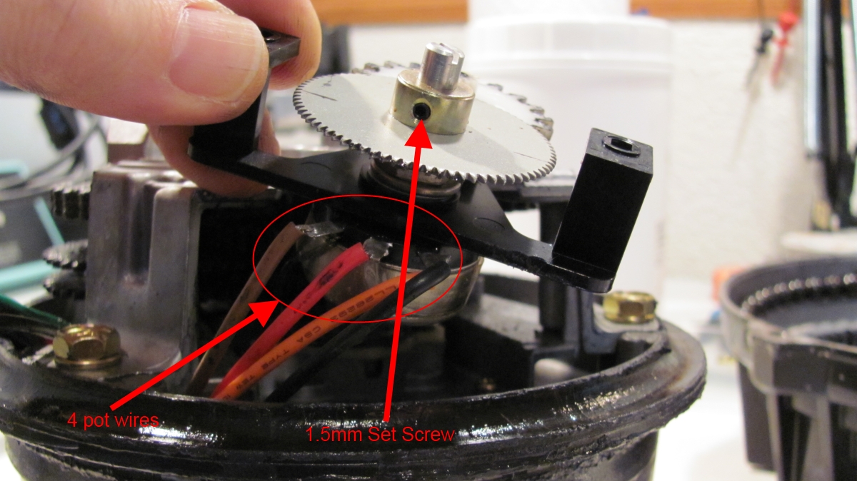
Step 8: Carefully slide the pot with Gears #1 and
#2 (items #45 and #47) out from the Gear Box Plate, and pull the wires and the pot
assembly out into the open.
Note the registration marks I made on Gear #1. This may be helpful to you during
reassembly.

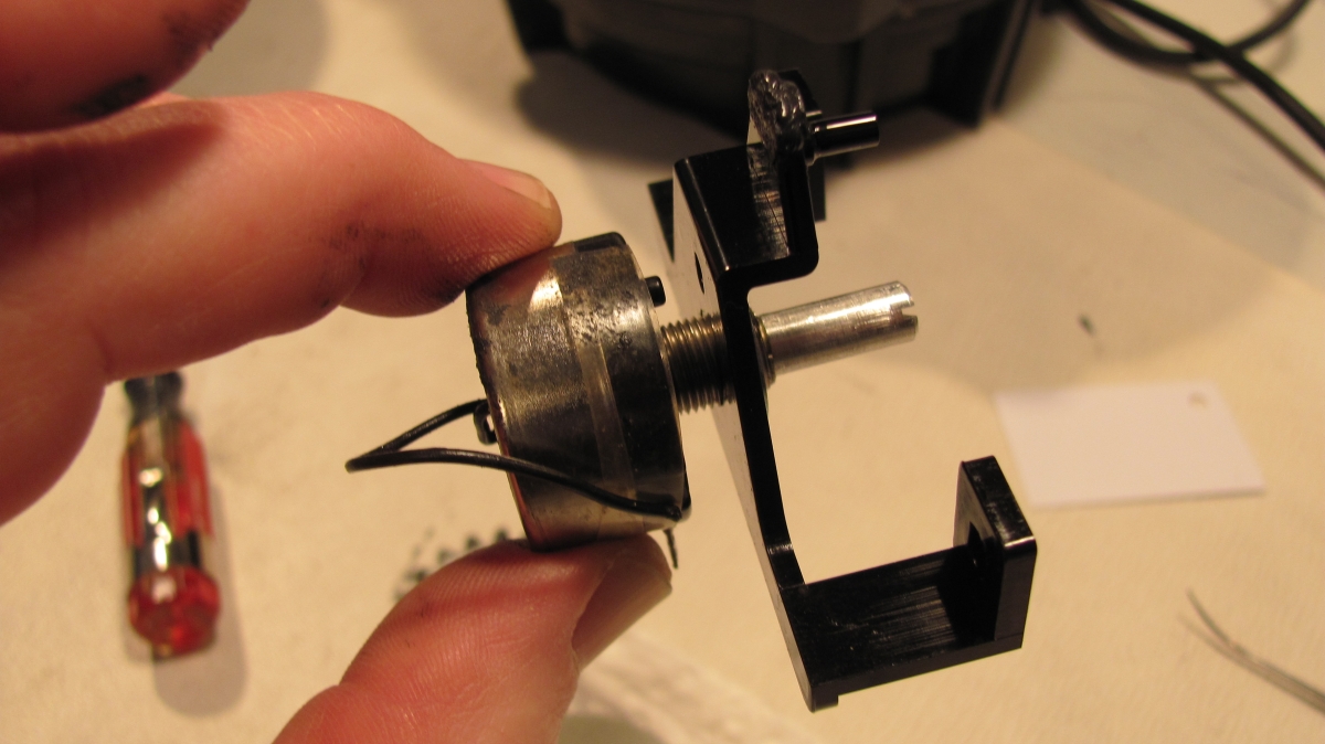
Step 9: Notice the 4 wires connected to the pot.
Pin #1 has the Brown wire soldered to it. This wire leads to pin #1 of the 7-pin
connector on the Lower Housing.
Pin #2 (wiper) has a Red wire soldered to it. This wire leads to pin #2 of the
7-pin connector on the Lower Housing.
Pin #3 has two wires: The Orange wire and a Black wire. The Orange wire leads to
pin #3 of the 7-pin connector on the Lower Housing. The Black wire leads to
Ground.
You can measure with an ohmmeter that the resistance between the Brown wire and
the Red wiper wire should be about 500 ohms since the rotor was set to fully CCW
before disassembly. Conversely, you should measure just a few ohms between the
Orange/Black wires and the Red wiper wire.
If your wire colors are different, make sure that you make note of them.
Desolder the wires from the leads on the pot.

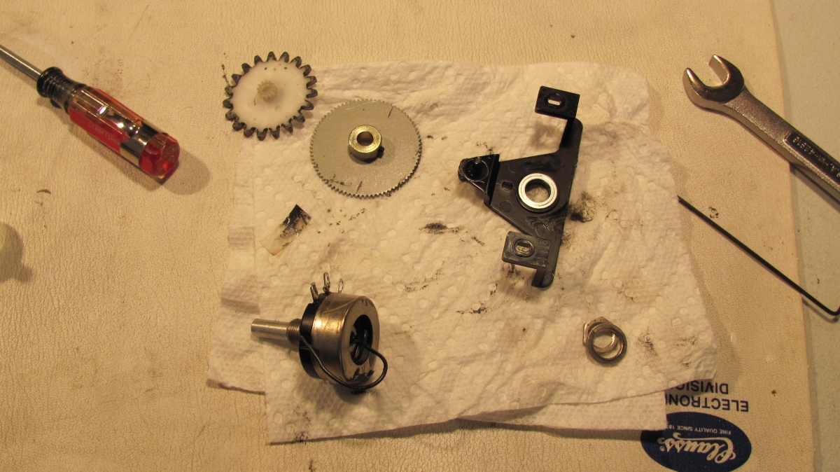
Step 10: Next you must remove the pot from the assembly and mount the
new one in its place.
Use a 1.5mm hex wrench to loosen the set screw on the collar (item #46) and
slide the collar and the Gear #1 (item #45) off of the end of the shaft on the
pot.
Remove Gear #2 (item #47).
Use a 12mm wrench to loosen and remove the nut that holds the pot to the
Mounting Plate (item #39).