
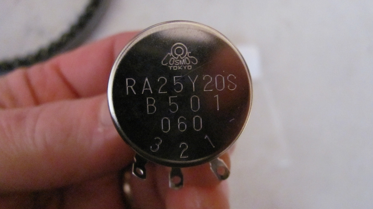

Step 11: Obtain the replacement pot. Make sure that you turn the wiper shaft fully clockwise so that it is in the same position as the one that you have removed. Solder the wires to the pot and assemble the new pot with the gears in reverse order.
Amateur Radio Station
WC0M
(Formerly: WC0EM, WF0GM)
Repairing a Yaesu G-1000DXA Rotor
(Part 2 of 2)
Here is where you
should take a look at
comments that Scott, AC8DE has made to avoid hitting the hard stop of the
potentiometer.
He discusses electrically centering the pot to avoid hitting the hard stop at
full rotation in either direction.
I did not have a problem with my rotor after I made my repair, but if I ever do
this again, I will use Scott's method which I believe is better than the method
that I used.
Step 11: Obtain the replacement pot. Make sure that you turn the wiper
shaft fully clockwise so that it is in the same position as the one that you
have removed. Solder the wires to the pot and assemble the new pot with
the gears in reverse order.
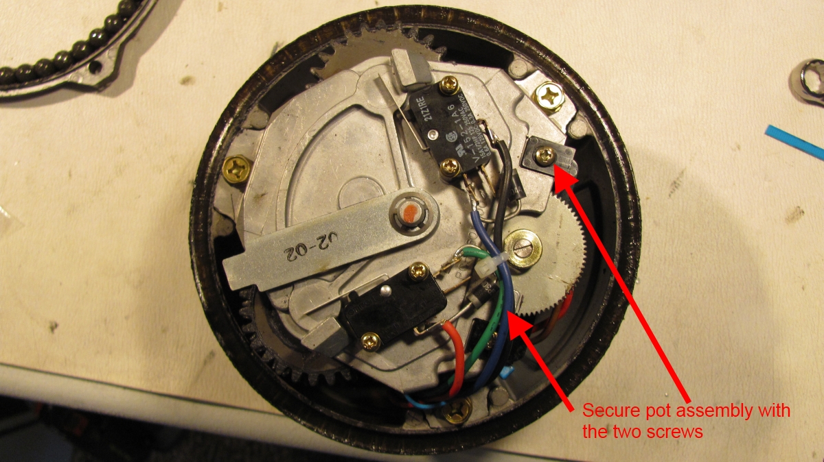
Step 12: Slide the pot assembly back onto the Upper Gear Box Plate (item
#33). Carefully guide the teeth of Gear #2 (item #47) into the mating gear
inside the gear box. Don't mesh the gears too much, allow a small amount of play
between gears. Your registration marks on Gear #1 (item #46) should line up very
closely with the edges of the Upper Gear Box Plate. Install the two screws and
snugly secure the pot assembly to the Upper Gear Box Plate, but do not over
tighten!

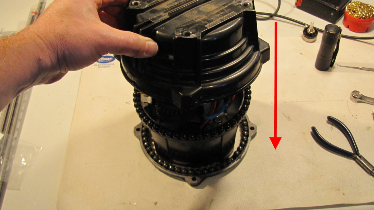
Step 13: Now it is time to put the Upper Housing (item #2) back on. Put the 49
ball bearings (item #5) back onto the upper race. The grease should hold them in place. If
you desire to put new grease on, this would be the time to clean it up and do
it.
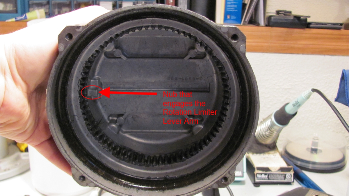
Move the Rotation Limiter lever arm (item #35) clockwise a couple of inches.
This must be far enough so that the nub on the Upper Housing will clear it and
falls between the lever arm and the CCW Limit Switch (item #37) when properly seated.
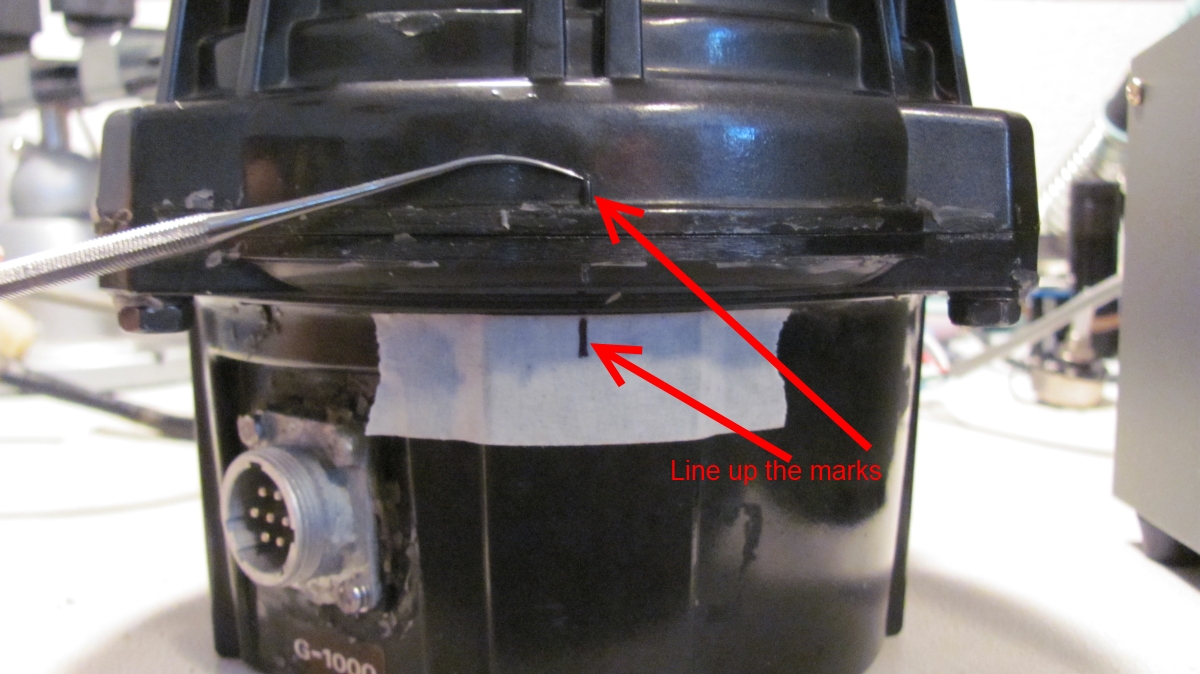
Line up the calibration mark on the Upper Housing with the mark you put on the
masking tape while lowering the Upper Housing onto the Lower Housing (item #1).
Step 14:
Connect the controller to the rotor housing. Turn on the controller and set the
rotation speed to minimum.
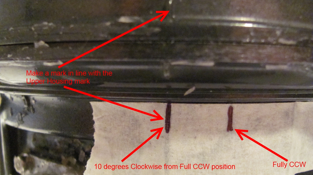
Hold the Upper Housing in place by putting downward pressure on it with one
hand, and rotate the Upper Housing about 10 degrees clockwise using the seesaw
switch with the other hand.
Turn off the controller. Disconnect the cables.
Make a new mark on the masking tape where the calibration mark is pointing.
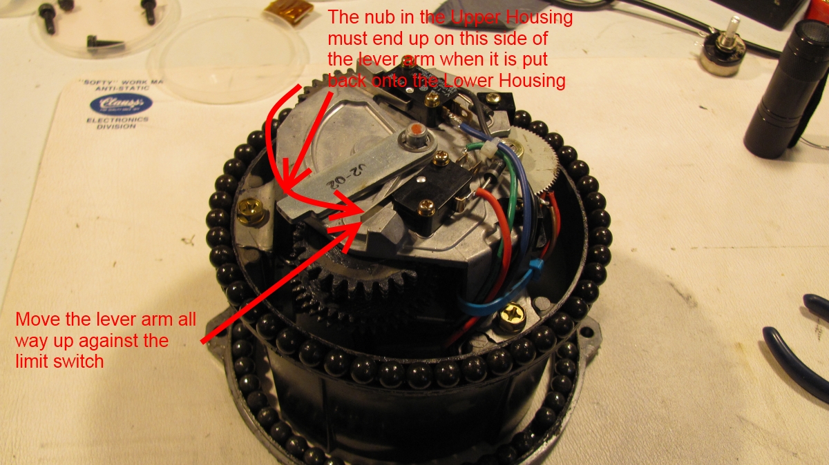
Step 15: Now remove the Upper Housing from the Lower Housing by lifting
the Upper Housing straight up as show in Step 5. Move the Rotation Limiter lever
arm (item #35) all the way up against the CCW limit switch (item #37). Put
the Upper Housing back onto the Lower Housing and make sure the mark on the
Upper Housing lines up with the 10 degree mark you made on the masking tape in
the previous step. The nub on the Upper Housing must end up on the left side of
the Rotation Limiter lever arm when the Upper Housing is put back onto the Lower
Housing.
Step 16: Now
connect the controller to the rotor and test it before bolting things back
together. Set the speed control to the slowest position so that the rotor moves
at it's slowest speed. While holding the Upper Housing down with one hand, and
your other hand pressing the seesaw switch on the controller, turn the rotor
back to the fully CCW position and make sure it stops turning when it reaches
the mark you have made on the masking tape at the fully CCW position. This will
tell you that you have the Rotation Limiter (item #35) lever arm, pressing the CCW limit switch (item #37) properly. Listen to the gears as it rotates. Stop if
something doesn't sound right!
Now turn the rotor all the way to the fully CW position. The nub on the Upper
Housing should swing around and push the Rotation Limiter lever arm all the way
up against the CW limit switch, and the rotor should stop. Again, listen to the
gears as it rotates. Stop if something doesn't sound right! If all looks good,
turn the rotor back to the fully CCW position again, then back CW 10 degrees to
your 10 degree mark.
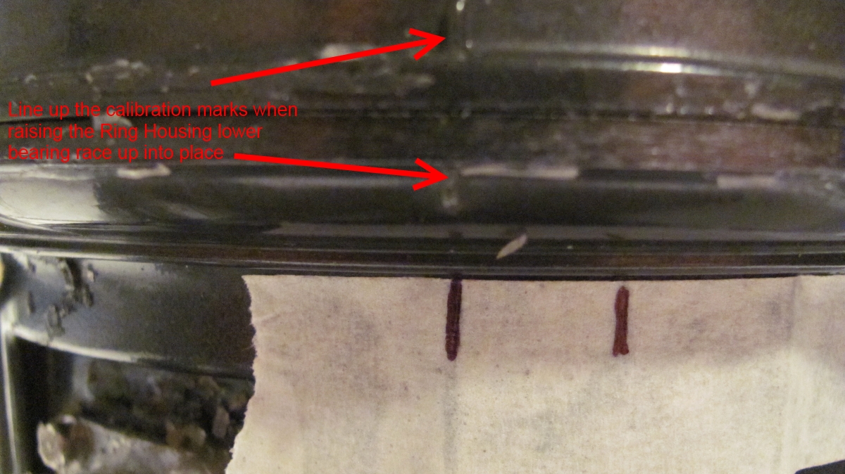
Step 17: Disconnect the controller cable from the rotor. Make sure
all 49 of the remaining ball bearings are placed onto the Ring Housing (item
#55) lower race. The grease should hold them in place. Raise the Ring Housing
lower bearing race up in place with the calibration mark on the lower race lined
up with the calibration mark on the Upper Housing.
Step 18: Now keeping the Ring Housing raised up
against the Upper Housing, squeeze the two together while flipping the rotor
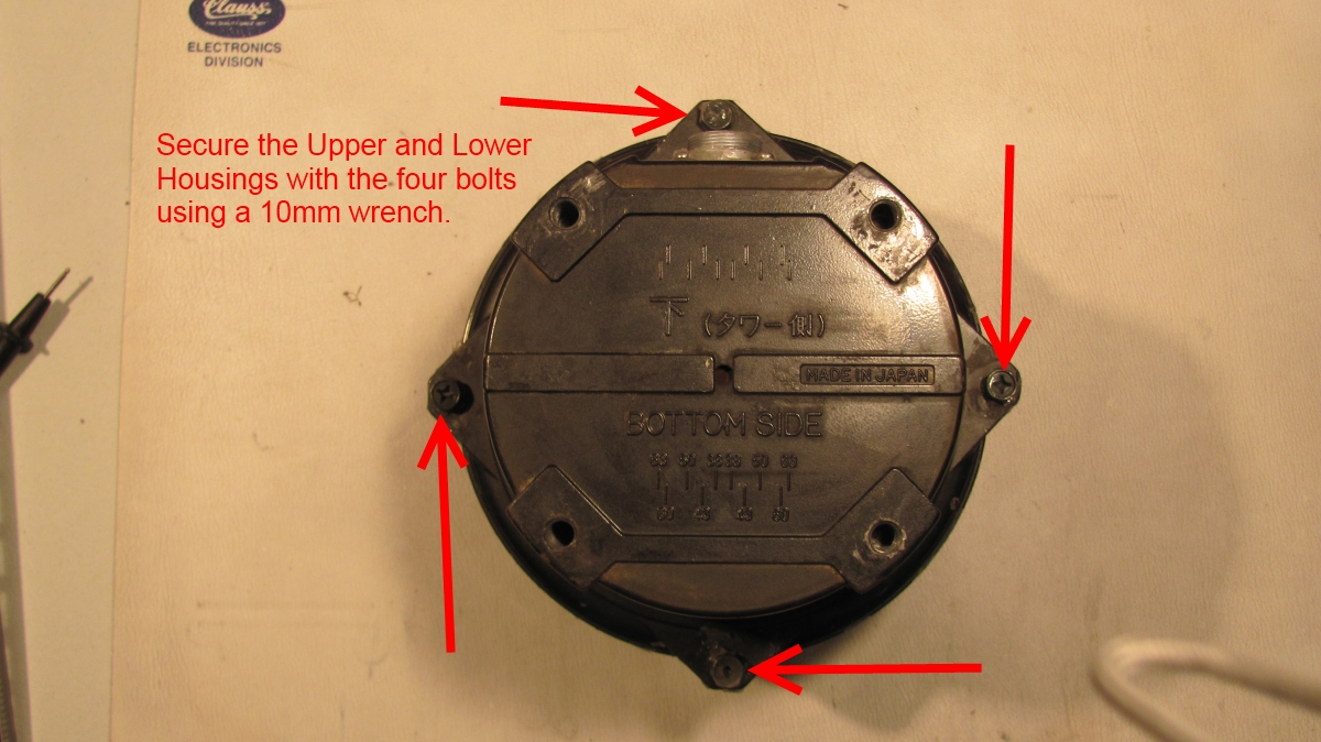
over onto it's top. Install the four 10mm bolts (item #4) through the
Ring Housing into the threaded holes in the Upper Housing. Secure the bolts
evenly and firmly into place, but do not over tighten!
Step 19: The
last thing to do is to connect up the controller to the rotor and do a final
check and calibration. Make sure the speed control is at the slowest position.
Turn the rotor back to the fully CW position. The nub on the Upper Housing
should swing around and push the Rotation Limiter lever arm all the way up
against the CW limit switch, and the rotor should stop. Now turn the rotor
all the way to the fully CCW position. Make sure it stops turning when it
reaches the mark you have made on the masking tape at the fully CCW position.
Now follow the calibration procedure detailed in the User Manual on page 8,
"Indoor Performance Check and Alignment".
Your rotor should now be as good as new and back in business!